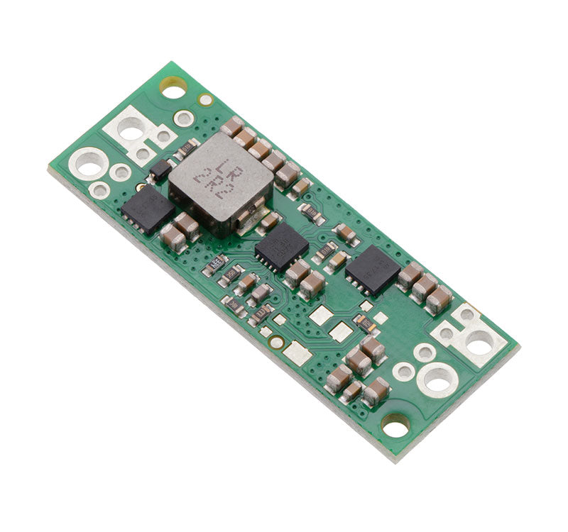
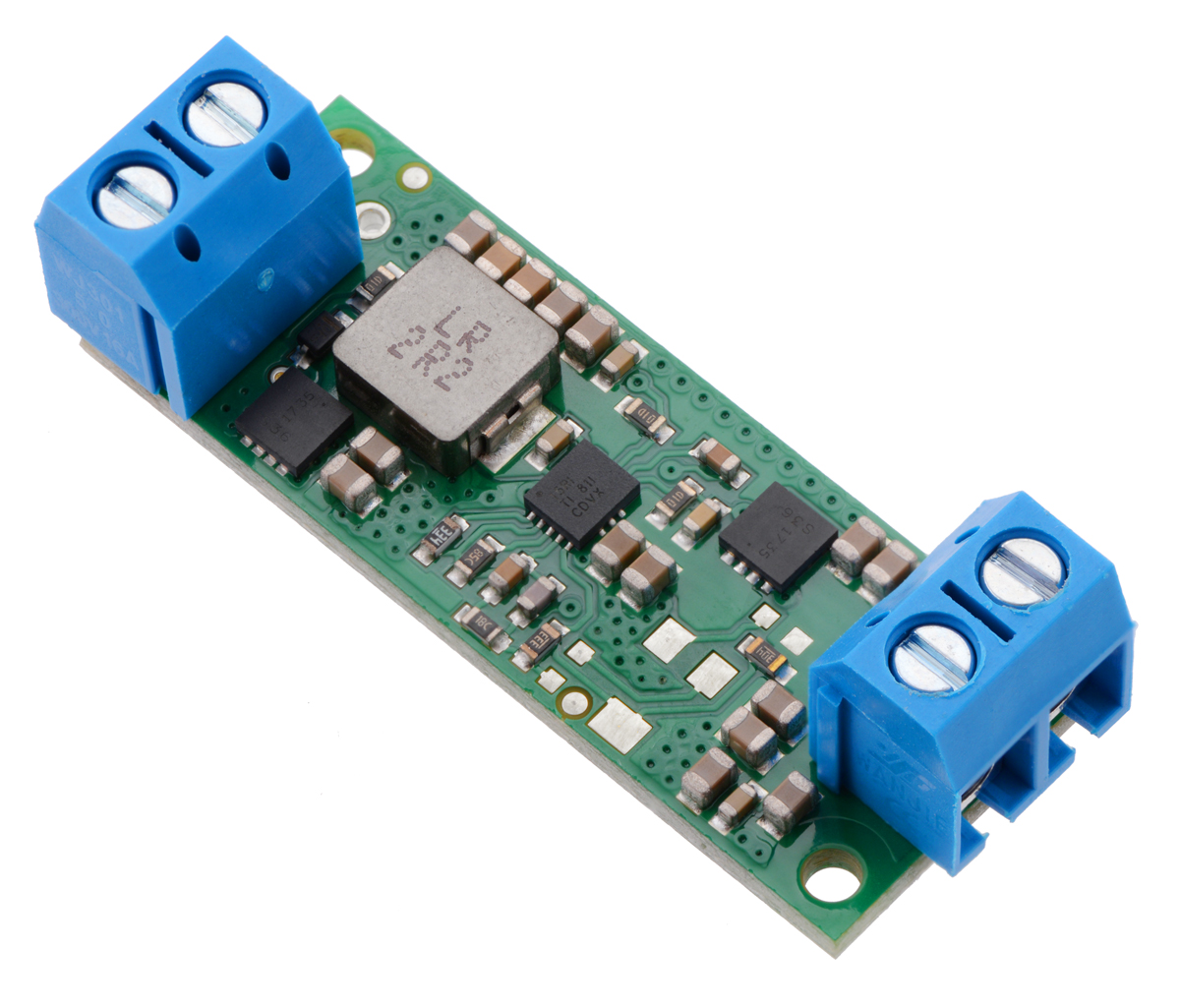
12V Step-Up Voltage Regulator U3V70F12
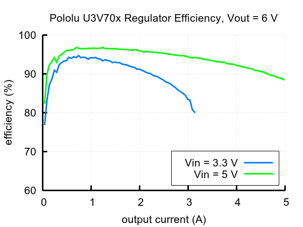
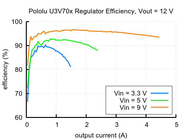
The U3V70x boost (step-up) voltage regulators are high-current, high-efficiency synchronous switching regulators that generate higher output voltages from input voltages as low as 2.9 V. The regulators actively limit the instantaneous input currents to 10 A, and the input current can typically be as high as 8 A for several seconds before the thermal protection activates. Input currents of around 6 A can typically be maintained for many minutes without triggering thermal shutdown, though the actual performance depends on depending on the input and output voltages as well as external factors such as ambient temperature and airflow. For boost regulators, the output current equals the input current times the efficiency times the ratio of VIN to VOUT, so the more you are boosting, the lower the maximum output current will be (see the Typical efficiencies and output currents section below for performance graphs).
These regulators feature a variety of built-in protections, including reverse voltage protection to keep your load safe in the event power is accidentally connected backward, and unlike most boost regulators, these units offer a true shutdown option that turns off power to the load (with typical boost regulators, the input voltage will pass directly through to the output when they are disabled).
Features and specifications
- Input voltage: 2.9 V to 12 V
- Output voltage: 12 V with 4% accuracy
- True shutdown option turns off power to the load
- Typical efficiency of 80% to 95%, depending on input voltage and load (see the Typical efficiencies and output currents section below for performance graphs)
- 10 A switch allows for:
- Instantaneous input currents up to 10 A
- Input currents up to 7 A for several seconds
- Input currents up to 6 A for prolonged durations
- low quiescent current
- Integrated protections:
- Reverse voltage protection
- Short-circuit protection with hiccup recovery
- Over-temperature shutoff
- Under-voltage lockout (typical thresholds are 2.4 V falling, 2.8 V rising)
- Cycle-by-cycle input current limiting to 10 A
- Compact size: 1.6? ?0.6? ?0.18? (40.6 ?15.2 ?4.6 mm)
- Weight: 3.5 g
- Two mounting holes for #2 or M2 screws
- Smaller holes for 0.1? header pins and larger holes for terminal blocks offer several options for connecting to the board
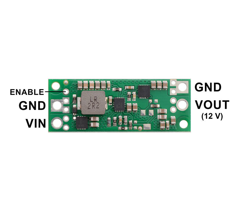
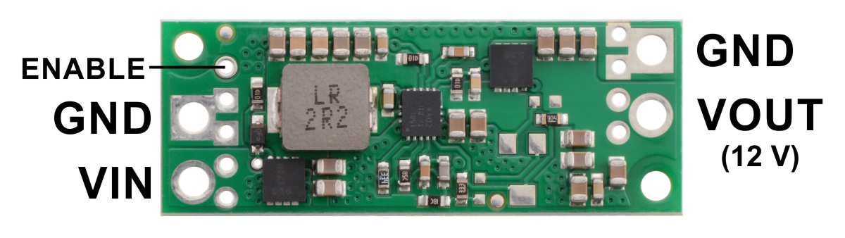
U3V70F12 connections
The input voltage, VIN, must be at least 2.9 V and should not exceed the output voltage, VOUT. (If VIN is higher than VOUT, the higher input voltage will show up on the output, which is potentially dangerous for your connected load and could also damage the regulator.)
The regulator is enabled by default: a 100 k? pull-up resistor on the board connects the ENABLE pin to reverse-protected VIN. The ENABLE pin can be driven low (under 0.4 V) to turn off power to the load and put the board into a low-power state. The quiescent current draw in this sleep mode is dominated by the current in the pull-up resistor from ENABLE to VIN, which will draw 10 µA per volt on VIN when ENABLE is held low, and by the reverse-protection circuit, which draws current when VIN exceeds 7 V. The current draw of the reverse-protection circuit is independent of the state of ENABLE and is given by (VIN – 7 V)/100 k?.
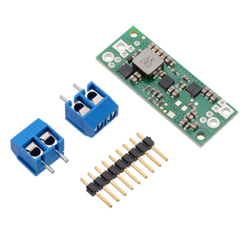
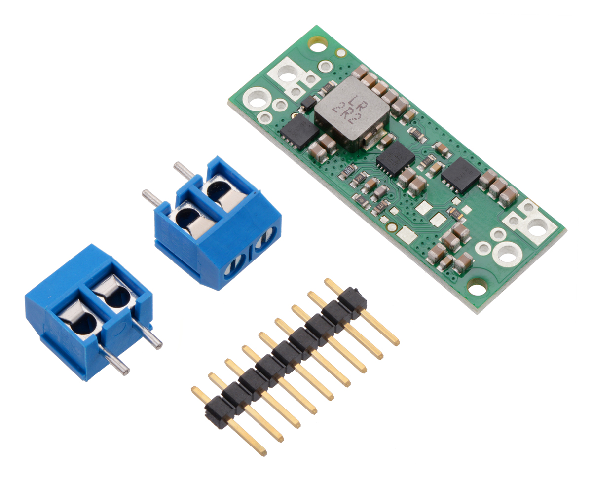
Included hardware
 |
| Step-Up Voltage Regulator U3V70Fx with included hardware. |
|
 |
| Step-Up Voltage Regulator U3V70Fx, assembled with included terminal blocks. |
|
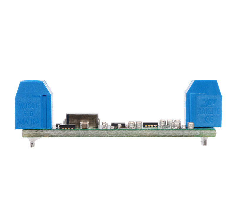
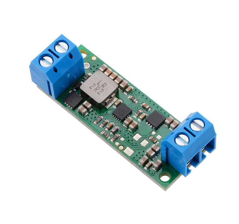
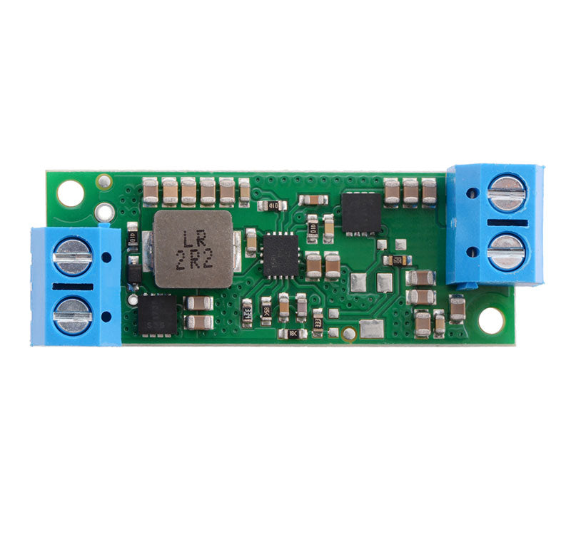
This regulator offers several options for making electrical connections. The nine smaller through-holes on the ends of the board are arranged with a 0.1? spacing for compatibility with solderless breadboards, connectors, and other prototyping arrangements that use a 0.1? grid. The included 0.1? male header can be broken or cut into smaller pieces as desired and soldered into these smaller through-holes. Alternatively, the included terminal blocks can be soldered into the larger holes to allow for convenient temporary connections of unterminated wires (see our short video on terminal block installation). You can also solder wires directly to the board for the most compact installation.
Typical efficiencies and maximum output currents
The efficiency of a voltage regulator, defined as (Power out)/(Power in), is an important measure of its performance, especially when battery life or heat are concerns. As shown in the graphs below, the U3V70x regulators have an efficiency of 80% to 95% for most combinations of input voltage, output voltage, and load.
The maximum achievable output current is approximately proportional to the ratio of the input voltage to the output voltage. Additionally, the maximum output current can depend on other factors, including the ambient temperature, air flow, and heat sinking. The graph below shows the typical maximum continuous output currents these regulators can deliver at room temperature with no forced airflow or heat sinking.
 |
| Typical maximum quiescent current of Step-Up Voltage Regulator U3V70x (regulator enabled, no load). |
Documents